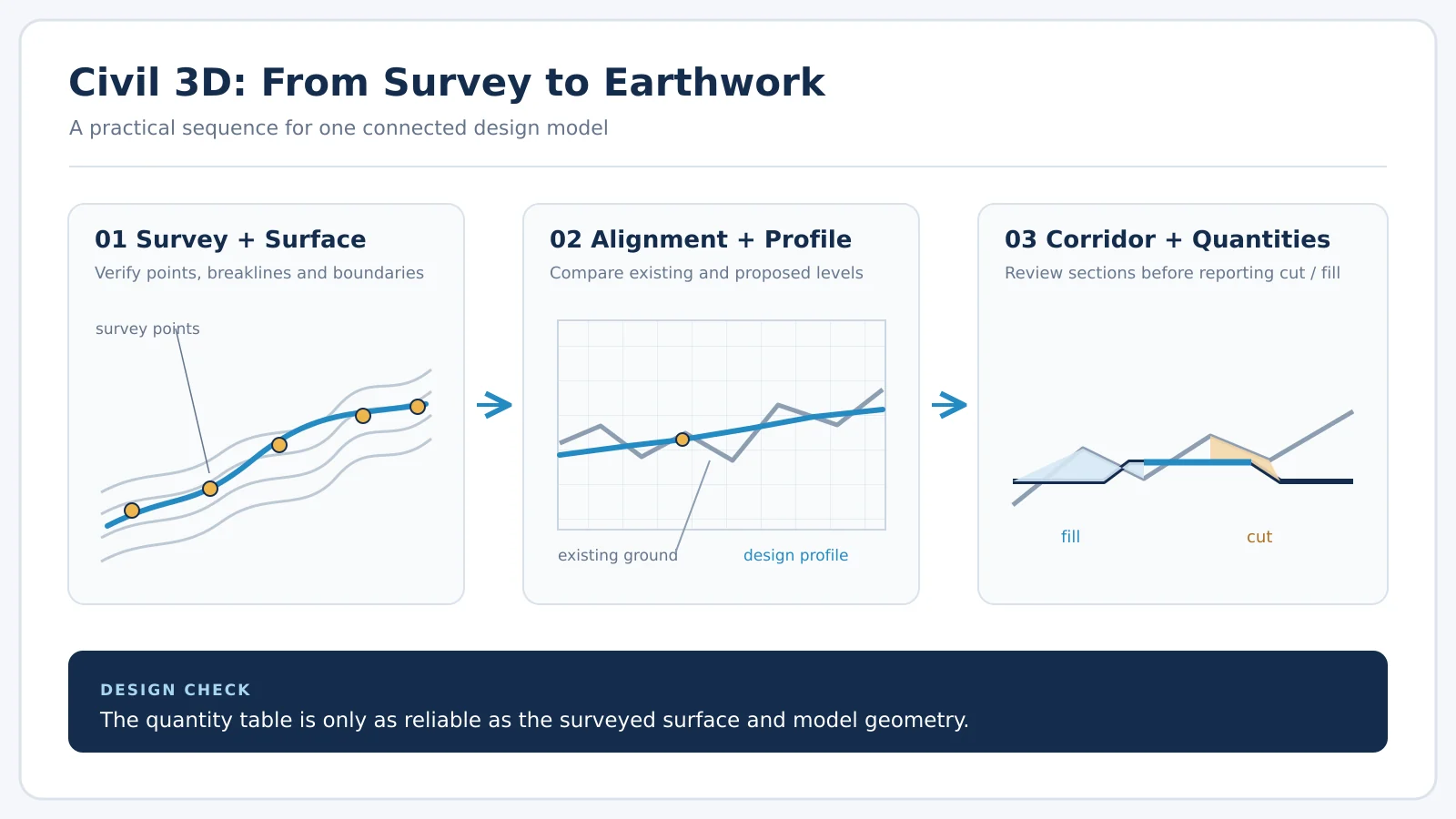
Learning Civil 3D is easier when the tools follow a real design sequence. A surface, alignment, profile, corridor and quantity table are connected decisions, not five unrelated commands. This guide outlines a practical workflow for a small road or site access project and points out the checks that matter before you trust the output.
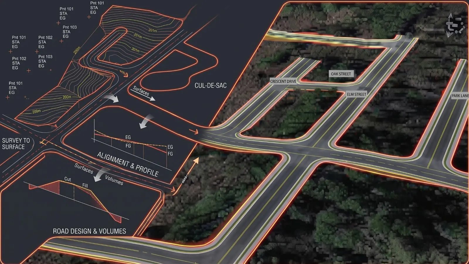
1. Set up the project before drawing geometry
Confirm the units, coordinate system, drawing template and file naming convention. Import survey points into well-named point groups and check their descriptions and elevations. A point that lands in the wrong location or uses the wrong elevation unit can undermine every object built from it. Keep the original survey file and record the assumptions behind any cleanup.
2. Build and review the existing ground surface
Create a TIN surface from the appropriate survey data. Add breaklines where the terrain changes sharply, then define a boundary so the surface does not triangulate across areas without evidence. Review contours, slope shading and spot elevations against the survey. Long triangles, unexpected spikes and contours crossing a curb or ditch are signals to inspect the source data before moving on.
3. Lay out the horizontal and vertical design
Create the alignment that represents the design baseline. Build an existing-ground profile from the surface, then draw a proposed profile while checking grades, vertical curves and tie-in elevations. The alignment controls where stationing and cross sections are taken; the profile controls the proposed elevations. If either changes, review all dependent objects rather than assuming the design still works.
4. Use an assembly and corridor to connect the design
An assembly describes the typical cross section. Apply it along the alignment and proposed profile to create a corridor. Set targets and regions deliberately, especially where widths or daylight conditions change. Inspect the model in plan, profile and section views. A corridor that looks plausible in plan may still contain an incorrect slope, target or transition in section.
5. Check sections and quantities
Use sample lines and section views to compare existing and proposed surfaces at meaningful intervals and critical locations. For earthwork, confirm the surfaces, boundaries, units and calculation method before reporting cut and fill. A quantity report is only as reliable as its underlying geometry. Record where assumptions or exclusions affect the result.
A useful beginner deliverable
For practice, finish one compact project with a reviewed existing surface, horizontal alignment, existing and proposed profiles, a corridor, several checked cross sections and a documented earthwork summary. Save an annotated drawing and a short list of unresolved design questions. This teaches how the Civil 3D objects depend on one another.
Autodesk’s documentation explains how corridors combine alignments, profiles, assemblies and surfaces, and how sample lines and section views support review of existing and proposed levels.
If you want to practise this sequence with guided exercises, see our Civil 3D Beginner to Intermediate course: 12 practical sessions followed by a complete final project.
Design challenge: a warning-free model is not an approved design
Imagine a short access road whose alignment passes Civil 3D’s criteria check, but a low point in the profile sends runoff toward a property entrance. The software check tells you something about the selected criteria file; it does not resolve drainage, access, utility conflicts or the approving agency’s project conditions. Before drafting, build a one-page criteria register: jurisdiction and document edition, road classification, design speed, grading and drainage constraints, survey datum, and who will confirm each assumption. Then review the low point and tie-ins in plan, profile and section together.
This matters across borders. The U.S. AASHTO Green Book is a geometric-design reference, while the UK’s DMRB serves specified trunk-road schemes and varies by overseeing organisation and contract date. Autodesk explains that Civil 3D can load local design-criteria files and flag violations. None of those files automatically becomes the approval standard for an Ontario municipal project. Identify the governing local criteria first; use U.S. and UK references to challenge assumptions and compare methods, not to import their minimum numbers unchanged.
Design challenge: quantities change when a corridor moves
Suppose the proposed profile rises to clear a utility, or the corridor’s daylight target changes at a property boundary. Which section views, surface boundaries and cut/fill volumes are now stale? Trace every dependent object, rebuild the corridor, inspect sections at the transition and recalculate volumes with the same comparison surfaces and units. Keep a short change log: what moved, why it moved, which drawings were refreshed and what remains unverified. A believable total volume without a traceable change history is not a strong deliverable.
Try this exercise: choose one difficult station in a sample road model. Show the existing ground, proposed profile, corridor section, drainage direction and one conflicting constraint on a single annotated sheet. Write two alternatives and explain which local criterion or field measurement would decide between them.
Discuss a difficult design step
If a surface, corridor, section or quantity result does not make sense, write down the exact station, input and assumption that causes the problem. BackToSkill’s Telegram channel and Facebook page share learning updates; separate English and Persian discussion groups will be linked after their setup is complete. A focused question helps peers and instructors respond usefully. Learning support does not replace a qualified engineer’s review or approval of a live project.